
Measuring Lost Motion at a Direction Change
Filed under: Workshop Notes
A pointer can start moving while the part it is meant to drive stays still. That small interval is a useful workshop question: where did the input movement go?
Raspberry Pi’s October 30, 2026 OuijaCNC account describes a concealed CoreXY mechanism moving a wooden planchette through magnetic coupling. The makers report difficulty overcoming friction and describe changes to the magnets, their mounting and the planchette’s support. Their account is a starting point for separating commanded movement from movement at the visible object. It does not supply a measured backlash result for the machine.
Name the mechanism you want to examine
Backlash is lost motion associated with clearance when a drive reverses direction. The LinuxCNC glossary describes this reversal-related play. A group can explore the idea without switching on a motor or diagnosing the published project.
The question is specific: after the input reverses, how far can it move before the output begins to follow? This differs from asking whether the final pointer position looks correct. A mechanism can reach a marked place while still having taken up a gap along the way.
Use a deliberately simple model
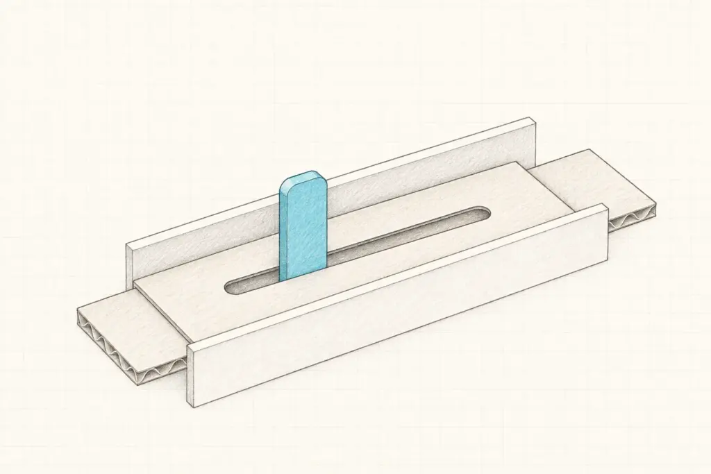
Prepare a small cardboard slider with a short horizontal slot. Place it on a paper base with loose paper guides that allow left-right movement. A blunt pointer inside the slot acts as the input; a mark on the cardboard acts as the output. Keep the pointer upright without pressing the slider against the base.
One person moves the pointer gently while another watches the output mark. The pointer first contacts an end of the slot and pushes the card. When its direction changes, it can cross the space inside the slot before contacting the opposite end. That is the interval to observe.
- Move in one direction until the card is clearly following the pointer.
- Reverse slowly. Mark the pointer position at reversal and again when the card begins to move the other way.
- Repeat several times, recording the gap between those marks and any trial in which the card sticks or twists. Use the same ruler and units throughout, and do not report detail finer than you can read.
Treat the distance as observed input travel before the card follows. Clearance contributes to it, but sticking, twisting and the observer’s judgement can also affect the reading. Keep the slot, pointer and guides unchanged while you compare repetitions. If you later change the slot width, record that as a new configuration rather than mixing the observations together.
State what the result leaves open
The model isolates an intentionally visible clearance. It does not reproduce a CoreXY transmission, quantify the OuijaCNC build or establish the cause of an error in another mechanism.
A real assembly may include friction, flexible parts, changing tension or a coupling that slips. Returning to the source, the makers’ friction problem is documented; calling it backlash would add a diagnosis that their account does not establish. The next useful test would have to distinguish movement of the drive from movement of the planchette.
End the session with two records: what moved in your model, and which part of that model corresponds to the question you want to investigate next. A measured gap is most useful when the group can explain exactly which gap it measured.
This is an optional, unpowered classroom model. It is not a calibration procedure or an instruction to modify a CNC machine.