
A level bar that changes its place
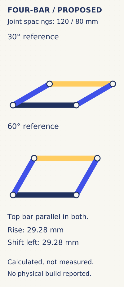
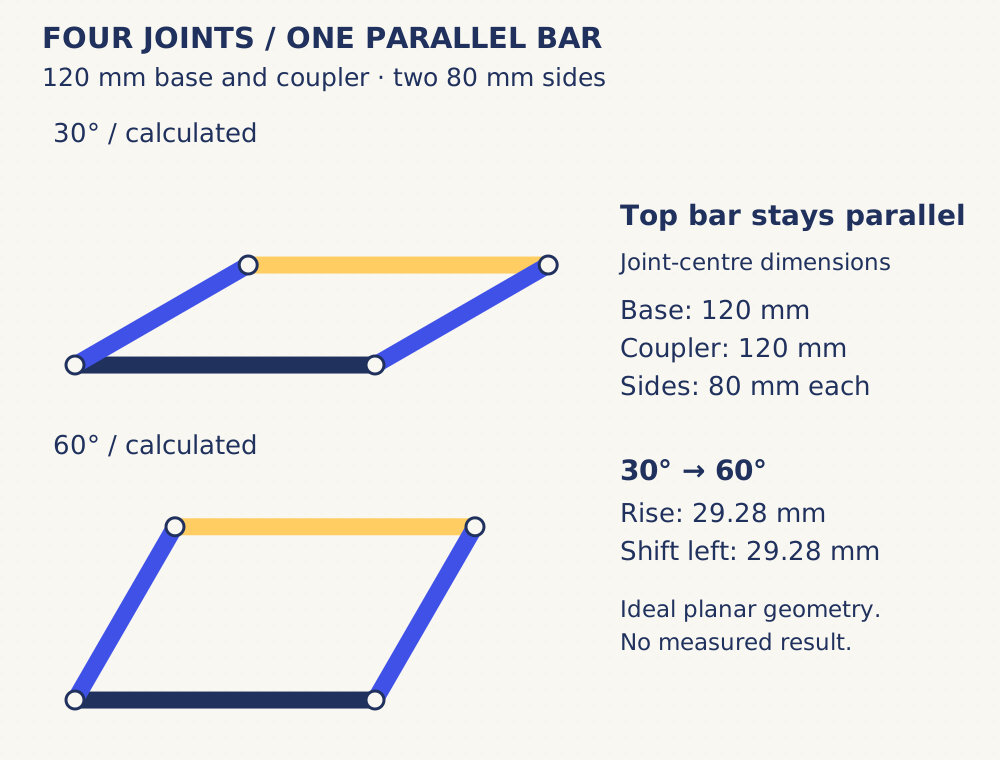
The lever study asks about travel and effort. This mechanism asks about orientation: can the top bar move while staying parallel to its base? Four links close a loop. The base and top bar each have 120 mm between hole centres; both side links have 80 mm.
The Carnegie Mellon mechanism text, §5.2.1, identifies the constant coupler orientation of a parallelogram linkage. The dimensions and proposed card build below are this edition’s example. No assembly or physical test is reported.
Cut by the holes, not the outside edge
Prepare two 136 × 20 mm card strips with holes 8 mm from each end: hole spacing 120 mm. Prepare two 96 × 20 mm side strips with the same end margins: hole spacing 80 mm. An adult prepares cuts and suitable holes. Use four paper fasteners through the four joints, leaving them loose enough to turn; keep small parts with the supervising adult.
Fix only the base strip to a backing sheet. Arrange the side links on the same side of the base, pointing up and right; attach the top bar to their free ends. Do not tape the moving links to the backing. Spacers may be needed where card faces rub; record any added layers and joint arrangement.
Two positions give a checkable prediction
Mark a horizontal base and two side-link reference directions, 30° and 60° above it. Move slowly between these positions in the open parallelogram arrangement. Do not force the links through an aligned or folded position; the limited range avoids treating a change of assembly branch as ordinary travel.
With the left base joint at (0, 0) mm, the top-left joint is (69.28, 40.00) mm at 30° and (40.00, 69.28) mm at 60°. The top-right joint is 120 mm to its right in each case. The top bar therefore rises 29.28 mm and moves left 29.28 mm in this ideal geometry, while its angle stays 0° relative to the base. Coordinates are rounded to 0.01 mm for the calculation, not a claim of card-build accuracy.
Record orientation separately from travel
- Version and actual hole spacings
- Date ____; base ____ mm; coupler ____ mm; left/right side ____ / ____ mm.
- At the first reference
- Actual side angle ____; left/right top-joint heights ____ / ____ mm.
- At the second reference
- Actual side angle ____; left/right top-joint heights ____ / ____ mm.
- Observation
- Height difference across top bar ____; rubbing, bending or loose joints ____.
Equal top-joint heights would support parallel orientation for that position; they would not measure load capacity or prove every point on a flexible strip stays level. Hole error, play and bending are candidate causes of a mismatch. Record them before revising.
The next test changes one question
This proposal carries no added load and uses no motor. Begin with whether the marked points follow the two reference positions. A later task could investigate joint clearance or load, with a new protocol. The gallery records assembly revisions; the handoff guide keeps the next builder’s starting state clear.